The gainclone, a minimalistic audio power amplifier inspired by, and sometimes copied from, the Model 4706 Gaincard amplifier from 47 Laboratory, has been around for more than fifteen years. Gainclones are attractive because of their simplicity ("world's smallest number of parts: nine per channel") and hence their low cost and accessibility for casual builders, coupled with the promise of big ticket performance.
Not all gainclones are equal; while some won favorable reviews, others disappointed their builders. I would like to explore - and hopefully clarify - some factors that affect the performance of gainclones and associated equipment, as well as ways to make building a great sounding amplifier an easy and enjoyable experience.
A gainclone is a Class AB audio power amplifier based on a power operational amplifier, or "opamp". The original Gaincard uses National Semiconductor's (now Texas Instrument) LM3875 chip, now obsolete. Gainclones have been built on the LM3875 but also on TDA2050 (also obsolete), LM1875, LM3886, LM4780, etc.
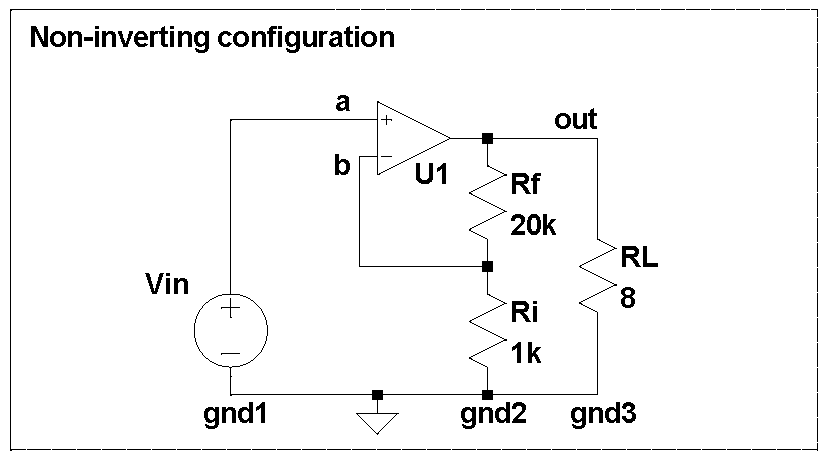
An opamp can be wired in different ways. The datasheets for all the chips listed above show, and virtually everyone uses, the non-inverting configuration:

In this configuration, the opamp U1 (such as an LM3886) drives its output so as to minimize the voltage between points (a) and (b):
V(a) - V(b) = 0, where
V(a) = Vin is the input signal and
V(b) = V(out) * Ri / (Rf + Ri) is the output signal scaled down by the divider formed by Rf and Ri.
If we rearrange the terms, we get amplification by a factor of k:
Vload = V(out) = k * Vin, where
k = (Rf + Ri) / Ri.
In a typical power amplifier, k is between 15 an 35.
The non-inverting configuration preserves the phase of the input signal, requires only two resistors, is commonly used in commercial and DIY amplifiers alike - what's not to like?
The devil is in that the non-inverting configuration quietly depends on a few assumptions that are worth to be examined. To start with, any voltage only makes sense if measured between two points. The reference point is often implicit and is usually called "the ground". If we make the reference point explicit, the equalities from above become:
V(a) - V(gnd1) = Vin
V(out) - V(gnd3) = Vload
V(b) = (V(out) - V(gnd2)) * Ri / (Rf + Ri) + V(gnd2)
When we solve these for Vload, we get
Vload = k * V(in) + distortion,
where distortion = k * V(gnd1) - (k - 1) * V(gnd2) - V(gnd3)
The silent assumption behind the non-inverting topology V(gnd1), V(gnd2) and V(gnd3) are exactly the same. If they are different, the amplifier can distort even if the opamp itself if perfectly linear!
In practice, it is surprisingly difficult to make V(gnd1), V(gnd2) and V(gnd3) equlal. If you simply connect the three points with a wire, any current flowing through that wire will create a voltage drop and will make gnd1, gnd2, and gnd3 differ.
Just how sensitive an amplifier is to this assumption? let us limit the distortion to 0.01% while delivering 1W RMS into 8ohm. 1W RMS into 8ohm requires Vload = Sqrt(1W * 8ohm) = 2.8V RMS. The distortion at 0.01% is equivalent to V(gnd3) = 280uV. The load current at 1W into 8ohm is 2.8V / 8ohm = ~350mA RMS. The resistance of 10cm (4inch) of 0.8mm (20AWG) solid copper wire is about 3mOhm, and the load current will create V(gnd3) = 350mA * 3mOhm = 1mV, or 0.035%. That is, connecting the bottom end of Ri to a wrong point can easily create distortion well above our self imposed limit.
The input is k times more sensitive; with k=20, V(gnd1) = 14uV equals to 0.01% of distortion.
If the difference between gnd1, gnd2, and/or gnd3 has enough of a 50/60Hz component, the amplifier may hum. If this current is the opamp's supply current, the amplifier will distort more, etc. Even if you make gnd2 and gnd3 one single point (a "star ground"), gnd1 may still be inside your preamp few feet away. Separating the three grounds may generate all kinds of problem, commonly called ground loop issues, for which there are more or less effective remedies and workarounds, to be discussed in a later post.
